


Nondestructive Testing of Generators During Planned Turnarounds
Waste-to-energy (WTE) facilities rely on turbine-driven generators to convert the thermal energy recovered from municipal waste into reliable electrical power for plant operations and export to the electrical grid. These generators operate continuously under demanding mechanical, thermal, and electrical conditions, making the integrity of critical components such as rotors, shafts, couplings, bearings, retaining components, and exciter assemblies essential to safe and dependable operation. Planned turnaround and outage periods provide an important opportunity to perform nondestructive testing (NDT) on normally inaccessible components without unnecessarily extending equipment downtime. The use of appropriate methods such as ultrasonic testing (UT/PAUT), magnetic particle testing (MT), liquid penetrant testing (PT), and eddy current testing (ET) can identify surface and subsurface discontinuities, including fatigue cracking and service-related degradation, before they progress to component failure. Incorporating NDT into the turnaround inspection program supports condition-based maintenance, reduces the risk of unplanned outages and costly equipment damage, and helps ensure the generator is suitable for continued service.

Potential failures in a brushless synchronous generator can occur in both rotating and stationary components as a result of cyclic loading, centrifugal forces, vibration, thermal cycling, wear, and localized stress concentrations. The main rotor and shaft may be susceptible to fatigue cracking or forging-related discontinuities, particularly at diameter transitions, fillets, keyways, radial holes, slots, and other highly stressed areas; UT, PAUT, and MT may be used to evaluate these locations. Shaft journals can experience fatigue cracking, scoring, wear, or overheating damage near journal transitions, bearing locations, and oil seal or deflector areas and may be examined using MT, ET, or PT. Couplings are subject to high- and low-cycle fatigue, with areas such as bolt holes, keyways, coupling teeth, hub-to-shaft transitions, and fillets being of particular concern; MT and UT/PAUT may be appropriate examination methods.
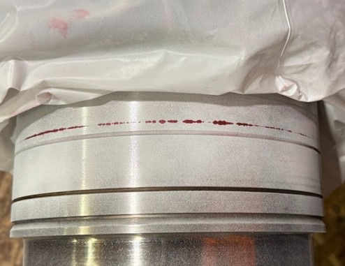
Rotor retaining rings may be susceptible to stress-corrosion and fatigue cracking, particularly at bore surfaces, shrink-fit areas, grooves, and geometric transitions, and can be examined using UT, ET, or PT as appropriate for the material and design. Rotor bodies and teeth may develop fatigue cracking at slot bottoms, tooth roots, and end regions, where UT, ET, or MT may be applicable depending on accessibility. The exciter rotor and shaft can similarly experience fatigue cracking at shaft transitions, keyways, and attachment locations and may be evaluated using MT and UT. Rotating rectifier or diode-wheel assemblies can experience cracking or mechanical loosening around hubs, bolt holes, and attachment points and may be examined using PT, MT, or UT where practical.
Generator bearings may experience babbitt cracking, separation, overheating, and wear, particularly within loaded regions, along edges, and at the babbitt-to-shell interface. VT, PT, and UT may be used depending on the condition being evaluated. Oil deflectors and seals can be affected by fatigue cracking, rubbing, or mechanical damage at bores, thin sections, attachment features, and bolt holes and may be examined using PT or MT depending on the material. Generator frames and end shields can develop fatigue or weld cracking at weld toes, mounting locations, and bearing supports and may be evaluated using VT, MT/PT, and UT where appropriate.
Stationary components can also experience service-related degradation. Stator cores and support structures may be affected by looseness, fretting, or cracking, particularly at structural supports and attachment welds, and can be evaluated using VT and MT/PT where applicable. Stator windings are more commonly affected by insulation degradation and conductor-related problems at end windings, slot exits, and electrical connections; these conditions are generally evaluated using visual and specialized electrical testing rather than conventional UT. Finally, the generator-to-turbine alignment system, including couplings, bearings, pedestals, and hold-downs, can experience cracking or fretting associated with vibration or misalignment. These areas may be examined using VT, MT/PT, and UT/PAUT as applicable, supplemented by dimensional alignment measurements and vibration analysis.
Liquid Penetrant Testing of Generators
Visible liquid penetrant testing (PT) is a practical method for detecting surface-breaking discontinuities in nonporous materials and is well suited for many generator components during turnaround inspections. The component surface is first cleaned and dried before a visible, typically red, penetrant is applied and allowed sufficient dwell time to enter cracks and other surface openings through capillary action. Excess penetrant is then removed, and a developer is applied to draw penetrant trapped within discontinuities back to the surface, producing visible indications that contrast against the developer background. Visible PT can be particularly useful for field inspection of nonmagnetic components, machined surfaces, welds, oil deflectors, bearing components, and other accessible areas where adequate white-light conditions can be maintained.
Fluorescent liquid penetrant testing uses the same basic principles but incorporates a penetrant that fluoresces when viewed under ultraviolet-A (UV-A) radiation in appropriately controlled ambient-light conditions. The high contrast of fluorescent indications can provide greater sensitivity to small or tight surface-breaking discontinuities, making the method useful for critical generator components where detection of fine fatigue cracking is important. Applications may include nonmagnetic rotating components, retaining components, machined surfaces, coupling features, exciter components, and other areas where magnetic particle testing is not applicable or PT is otherwise specified. For both visible and fluorescent PT, proper surface preparation, penetrant dwell, excess penetrant removal, development, lighting, inspection, and evaluation are essential to obtaining reliable results, and the examination should be performed in accordance with the applicable procedure, code, specification, and OEM requirements.
Magnetic Particle Testing Limitations
Although magnetic particle testing (MT) can provide a fast and highly sensitive method for detecting surface and near-surface discontinuities in ferromagnetic generator components, liquid penetrant testing (PT) may be preferred for certain assemblies because of concerns associated with introducing magnetic particles into adjacent components. Areas such as fan hubs and retaining rings may contain tight clearances, recesses, ventilation passages, joints, or other features where dry powder or wet magnetic particles can migrate and become trapped. Complete removal of these particles following the examination can be difficult, particularly when portions of the assembly are inaccessible. Residual particles can create a cleanliness concern and may potentially migrate into other areas after the generator is returned to service.
PT provides an alternative surface examination method that avoids introducing magnetic particles into these sensitive areas. While PT generally requires more time for surface preparation, penetrant dwell, removal, development, and final cleaning, the liquid materials can be more readily controlled and removed from accessible inspection surfaces when an appropriate procedure is followed. For this reason, PT may be selected even when MT would otherwise be faster and easier to perform, particularly where contamination of the fan hub, retaining ring, or adjacent generator components is a concern. The selection between PT and MT should ultimately consider component material, geometry, accessibility, required sensitivity, cleanliness requirements, OEM recommendations, and the applicable inspection procedure.
Phased Array Ultrasonic Testing of Power Generators
Phased array ultrasonic testing (PAUT) can be used to examine critical generator components for internal and surface-connected discontinuities, particularly in areas where fatigue cracking may develop. Unlike conventional UT using a single-element transducer, a phased array probe contains multiple elements that can be electronically pulsed in controlled sequences to steer and focus the ultrasonic beam through a range of angles. This allows a single probe position or encoded scan to interrogate the component from multiple sound paths and orientations. On generator components such as shafts, rotor forgings, couplings, fan hubs, retaining components, and other heavy-section parts, PAUT can be configured to target areas of elevated stress such as fillets, diameter transitions, bolt holes, bores, keyways, and other geometric features where cracking may initiate.
PAUT also provides encoded and recordable inspection data that can be displayed as A-scans, S-scans, B-scans, and C-scans, allowing indications to be evaluated in relation to their position within the component. Where geometry permits, multiple beam angles can improve detection and characterization of planar discontinuities that may not be favorably oriented to a single conventional ultrasonic beam. Scan plans should be developed using the component geometry, material, expected discontinuity orientation, and available inspection surfaces to establish appropriate probe locations, focal laws, coverage, and sensitivity. Calibration and examination should be performed using representative reference standards and an approved procedure, with acceptance criteria established by the applicable specification, OEM requirements, or owner-defined inspection criteria.

Eddy Current Testing of Generators
Eddy current testing (ET) can be used to detect surface and near-surface discontinuities in electrically conductive generator components without introducing penetrant or magnetic particles into the assembly. An alternating current in the probe coil produces an electromagnetic field that induces circulating eddy currents in the component. Cracks, material changes, or other discontinuities disturb the flow of these currents and produce a measurable change in the probe response. For generator inspections, ET can be particularly useful on retaining rings, fan hubs, shaft surfaces, bores, bolt holes, coupling features, and other machined surfaces, especially where fatigue or stress-corrosion cracking may be a concern. Specialized probes can also be selected to examine difficult geometries such as holes, grooves, radii, and recessed surfaces.
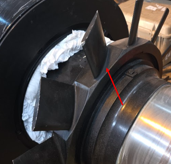
ET offers several advantages during generator turnaround inspections because it is relatively fast, requires minimal surface preparation, and does not require couplant or leave magnetic particles or penetrant materials behind. This makes it attractive in areas where cleanliness and the potential for inspection media to become trapped within the fan hub, retaining ring, or other closely fitted components are concerns. Encoded or array eddy current techniques can also provide recorded data and improve coverage of larger or complex surfaces. However, ET is generally limited to surface and relatively shallow subsurface examination, and results can be influenced by material conductivity, permeability, geometry, lift-off, coatings, and surface condition. Proper probe selection, calibration on representative reference standards, and qualified procedures are therefore important for reliable detection and evaluation.
Summary
Nondestructive testing plays an important role in assessing the condition of critical brushless synchronous generator components during planned turnaround and outage periods. A combination of PT, MT, PAUT, and eddy current testing can be selected based on component material, geometry, accessibility, expected damage mechanisms, and cleanliness requirements. PT and MT provide effective detection of surface-breaking discontinuities, although PT may be preferred in areas such as fan hubs and retaining rings where residual magnetic particles could become trapped within the assembly. PAUT provides volumetric examination of components such as shafts, rotors, couplings, and hubs and can target critical geometries using multiple electronically controlled beam angles, while eddy current testing provides rapid detection of surface and near-surface discontinuities without introducing inspection media into the assembly. When properly applied using qualified procedures and appropriate acceptance criteria, these complementary NDT methods can identify service-related degradation before it progresses to component failure, supporting reliable operation and reducing the potential for unplanned outages.
References
ASTM International. ASTM E1417/E1417M, Standard Practice for Liquid Penetrant Testing. ASTM International, West Conshohocken, PA.
ASTM International. ASTM E1444/E1444M, Standard Practice for Magnetic Particle Testing for Aerospace. ASTM International, West Conshohocken, PA.
ASTM International. ASTM E709, Standard Guide for Magnetic Particle Testing. ASTM International, West Conshohocken, PA.
ASTM International. ASTM E2491, Standard Guide for Evaluating Performance Characteristics of Phased-Array Ultrasonic Testing Instruments and Systems. ASTM International, West Conshohocken, PA.
ASTM International. ASTM E2700, Standard Practice for Contact Ultrasonic Testing of Welds Using Phased Arrays. ASTM International, West Conshohocken, PA.
ASTM International. ASTM E2375, Standard Practice for Ultrasonic Testing of Wrought Products. ASTM International, West Conshohocken, PA.
ASTM International. ASTM A388/A388M, Standard Practice for Ultrasonic Examination of Steel Forgings. ASTM International, West Conshohocken, PA.
ASTM International. ASTM A275/A275M, Standard Practice for Magnetic Particle Examination of Steel Forgings. ASTM International, West Conshohocken, PA.
ASTM International. ASTM E1004, Standard Test Method for Determining Electrical Conductivity Using the Electromagnetic (Eddy Current) Method. ASTM International, West Conshohocken, PA.
ASME. Boiler and Pressure Vessel Code, Section V – Nondestructive Examination. American Society of Mechanical Engineers, New York, NY.
ASNT. ASNT Nondestructive Testing Handbook, Volume 2: Liquid Penetrant Testing. American Society for Nondestructive Testing.
ASNT. ASNT Nondestructive Testing Handbook, Volume 5: Electromagnetic Testing. American Society for Nondestructive Testing.
ASNT. ASNT Nondestructive Testing Handbook, Volume 7: Ultrasonic Testing. American Society for Nondestructive Testing.
IEEE. IEEE Std 62.2, Guide for Diagnostic Field Testing of Electric Power Apparatus—Electrical Machinery. Institute of Electrical and Electronics Engineers.
Generator OEM inspection and maintenance manuals, service bulletins, drawings, and acceptance criteria, as applicable to the specific generator manufacturer, model, and component being examined.


Before talking to any agency I wanted a short checklist of what to ask. The post at https://www.explore.agency/blog/roofing-marketing-agency has five useful questions: whether they report cost per booked job, who owns the accounts and data, whether they have named roofing case studies, if paid media/SEO/website sit under one team, and how attribution works across ads, site, and CRM. It also flags common red flags like ranking guarantees and reports with no revenue column. Straightforward guide if you’re evaluating partners and want to avoid another round of vague monthly reports.